Installation Instructions
Please fill out a Quote Request and one of our experts will contact you quickly.
This is a .pdf of the Snobar ColorBar ColorRail and Metal Roof WindGuard Installation Instructions. For your convenience it is available for download.
Snobar-Windbar Install Instructions.pdf
Adobe Acrobat document [1.0 MB]
Before Installing the
SNOBAR COLORBAR COLORRAIL METAL ROOF WINDGUARD Systems
*Except where mentioned, installation instructions are the same for all systems. These instructions use Snobar for example.
Read the DESIGN CONSIDERATIONS, and make sure the roof panels you are attaching to are properly attached to the structure at a fixed point (See note in Fig. 2). This does not mean the clips, clips do not fix the roof panels, the standing seam panels must be attached with enough fasteners to withstand the added load incurred by the retained snow.
Required Tools: Make sure to have the proper tools for installing the SNOBAR system.
Rubber Mallet, Drill Gun, Torque Wrench (to tighten set screws to 90 in/lbs), Allen Bits, Nut Driver (size is 5/16”), Flex Driver, Chalk Line, Tape Measure, Hack Saw, and File to De-bur.
Make sure you have all the SNOBAR parts: Check packing slip with the Clamps, Bars, Set Screws (See note below about TWO screws per clamp), Tek Screws, End Caps, Optional Ice/WindStoppers (if ordered with your project).
Determine if your roof panel seam requires ONE SET SCREW or TWO SET SCREWS (See Figure 1). If your roof panel is a mechanically seamed roof with a single lock (such as, AEP Span-Lok, Butler VSR, MBCI Batten-Lok, American Buildings Lok-Seam, etc.), you only need ONE SET SCREW, and your job was only provided with ONE SET SCREW PER CLAMP. All other seam types require TWO SET SCREWS.
Make a layout plan of where the SNOBAR System is needed on the roof before starting installation. If additional rows of SNOBAR System are needed on the roof or certain roof areas (based on Design Considerations) make sure to layout and space the additional rows equally up the roof slope (see Fig. 2). For example, if the roof from eave to ridge is 26’-0”, and your were putting two rows of SNOBAR System on, you would put the first row at 12” up from the eave, and the second row would be put at 13’-6” from the eave (or 12’-6” from the first bar).
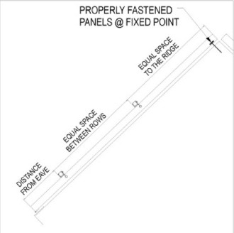 Figure 2
Lastly, before installing the SNOBAR System make sure you are properly tided off with the correct safety equipment/harness for working on sloped roofs. NEVER use the SNOBAR System as a tie off point or support for safety.
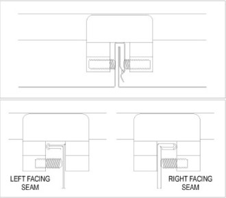 Figure 1
1. For seams using TWO SET SCREWS. Screw the Set Screws into the clamps equidistant, leaving just enough room for the clamp to installed onto the seam. For seams needing only ONE SET SCREW determine how the clamp direction is going based on how roof panel seams face (See Fig. 1) and partially screw in the set screw into ONLY ONE side of the clamp.
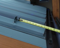 Figure 4
2. Based on the layout, measure 12” to 18” from the eave line to the first row of SNOBAR (if there is a overhang, place the first row of SNOBAR at the bearing wall).
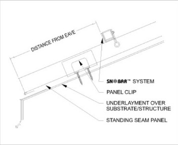 Figure 3
Make sure there is no panel clip at the location so that the SNOBAR will not fix the panel (See Fig. 3) NOTE: In a case where the metal roofing system has
two piece floating clips to allow for thermal movement, the SNOBAR clamp can be placed at the clip.
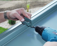 Figure 5
3. Set first clamp in proper orientation to roof slope (See Fig. 3 and 4). Hand tighten Set Screws to seam, making sure clamp is centered and bottom of clamp is down tight on top of seam. While putting downward pressure on the clamp, torque one of the two set screws to 90 in/lbs (See Fig. 5).
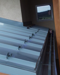 Figure 6
4. Based on a twelve foot long bar, set opposite end clamp per steps 2 and 3. Once clamp is in place, snap chalk line between the two clamps for placement of the remaining clamps. Install the remaining clamps on each seam per step 3 (See Fig. 6). During installation of the clamps, periodically check the set screws of previously installed clamps for proper torque.
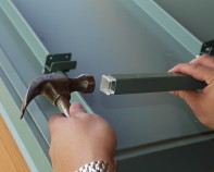 Figure 7
5. Install Plastic End Caps at each end of bar. Be sure to de-bur any field cut bars prior to installing End Caps (See Fig. 7).
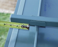 Figure 8
6. Place bar in clamps, making sure that the end of the bar does not extend past clamp more than 3” (See Fig. 8).
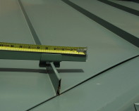 Figure 9
The 3” rule applies to the beginning of the bar as well as in valley areas (See Fig. 9).
 Figure 12
When in a continuous run do not extend the bar more than half of the width of the panel (See Fig. 12).
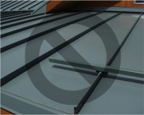 Figure 10
NOTE: Bar may have to be cut to length depending on panel width so that the bar never cantilevers more than half a panel width in a continuous run or more than 3” at the end/beginning of the bar and in the valleys (see Fig. 10 as to what NOT TO DO).
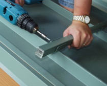 Figure 11
7. Making sure the bar is seated tightly in the first clamp, apply downward pressure to bar while installing two (2) Tek Screws through the back of the clamp (See Fig. 11). Follow the same procedures for the opposite end. Then, install the tek screws in the remaining clamps, ensuring that the bar is seated in the clamp and that the clamp is level and flush with the seam. NOTE: When using Stainless Steel Bar, at times, you might have to pre-drill the Tek Screw holes with a #30 drill bit (1/8”) prior to installing the Tek Screws.
 Figure 14
8. If a short run of SNOBAR is needed, make sure to span at least two seams. In a continuous run of SNOBAR, you may have to cut a bar so that you do not end up with a short bar at one seam. One clamp and a short bar clamped on one seam is not acceptable (See Fig. 14 as to what NOT TO DO)
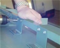 Figure 13
9. When the optional Ice/WindStoppers are used, make sure the Ice/WindStopper has the Tek Screw holes on the upslope side of the bar and is seated in the middle of the panel tightly onto the bar, apply downward pressure to Ice/WindStopper while installing the two (2) Tek Screws through the back of the Ice/WindStopper (Fig. 13). For panel widths 24” or less use one (1) Ice/WindStopper per panel and for greater the 24” use two (2) Ice/WindStoppers per panel. Typically, Ice/WindStoppers are only installed on the first run of SNOBAR above the eave line.
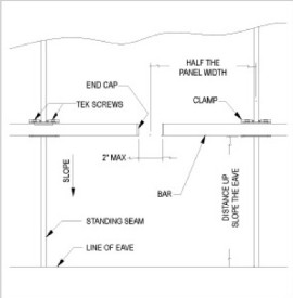 Figure 12
10. Repeat steps 4 through 8 until continuous bar is in place. Always make sure that the end of the bar does not exceed more than half the width of the panel or that the ends of the bars are no further apart then 2” (See Fig. 12). This means for certain width panels, the bars may have to be field cut by 4” to 12”.
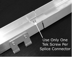 Figure 15
11. When continuing a run of SnoBar/Metal Roof WindGuard, install the next bar so that its plastic end cap butts up against the first snugly. When continuing a run of ColorBar/ColorRail, slide the provided splice connector halfway into the top channel of the first bar and fasten using a single Tek Screw. Slide the next piece of bar onto the remaining exposed splice connector to create a bridge and butt the two bars together snugly. DO NOT screw fasten the second
bar to the splice connector. This will allow the bar system to expand and contract depending on weather conditions. (See Fig. 15)
12. For additional rows of SNOBAR up the slope, repeat steps 3 through 9. Make sure that if multiple rows of SNOBAR are needed on a roof or in certain areas, always space them equally up the roof slope. For example, if you have a 31’-6” panel length from eave to the ridge that requires three rows of SNOBAR, place the first row of SNOBAR 18” up from the eave and the second row 10’-0” up from the first row of SNOBAR, then place the third and final row at 10’-0” up from the second row (or 21’-6” up from the eave).
"Now In Stock"
SnoBar Colorbar WindBar
* Same Day Pickup
* Online Ordering
* Super Fast Shipping
* Colors in 4 Weeks