
Technical Data
Center Of An Area
The center of an area, or centroid, of a shape is the point at which it is in equilibrium. If it is supported at this point it is in a state of equilibrium and should not fall off. A useful analogy that helps understanding this idea may be found by considering the center of gravity or center of mass. The center of different shapes cut out from a card board can be found by hanging it from a string. The line of action will always pass through the center of gravity of the particular shape. The principle is shown in the Figure below.
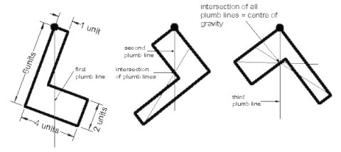
Note: The center of gravity is not necessarily within the body of the shape, it can fall outside as with most angular shapes. A more precise procedure to find the center of gravity is the first moment of area method. The position of the center of gravity of a compound body can be found by dividing the body into several parts where the center of gravity of the individual parts are known.

The following method applies:
- Divide the body into several parts (A1&A2).
- Determine the area (or volume) of each part.
(A1=4×1; A2=4×2) - Establish a reference point for taking moments (bottom left corner 0)
- Determine the distance from the reference point to the center of gravity of the individual parts (A1 x=0.5, y=1.0, A2 x=2.0, y=1.0)
- Take moments about the x-axis and y-axis to determine the center of gravity of the whole body as seen in the table below.
Example of the first moment of area method
The easiest way is to organize all data in a table as shown below:
|
Dimensions |
Area |
Distance to |
Area Moment |
||||
|
Length |
Width |
Units |
x-direction |
y-direction |
x-axis |
y-axis |
|
|
4 |
1 |
A1 |
4 |
0.5 |
4 |
2 |
16 |
|
2 |
4 |
A2 |
8 |
2.0 |
1 |
16 |
8 |
|
Area |
12 |
Area Moment |
18 |
24 |
|||
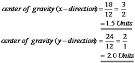
The center of gravity is found by dividing the specific area moment (x- and y-direction) by the total area and therefore:
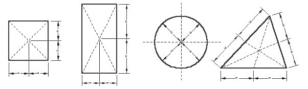
Centroids of Common Symmetrical Shapes
Second Moment of Area (I) or Moment of Inertia
The second moment of area (I) about a given axis is the sum product of the area and the square of the distance from the centroid to the axis.
The second moment of area or moment of inertia (I) is expressed mathematically as:
Ixx = Sum (A) x (y2)
|
Where |
Ixx |
= the second moment of area (moment of inertia) around the xx-axis |
|
|
A |
= the area of the plane of the object |
|
|
Y |
= the distance between the centroid of the object and the x-axis |
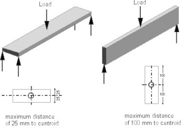
The second moment of area (I) is an important figure that is used to determine the stress in a section, to calculate the resistance to buckling, and to determine the amount of deflection in a beam. Let us look at two boards to intuitively determine which will deflect more and why. If two boards with actual dimensions of 200 by 50 mm were laid side by side - one on the 50mm side and the other on the 200 mm side. The board that is supported on its 50 mm edge is considerably stiffer than that supported along its 200 mm edge. Both board have the same cross-sectional area, but the area distributed differently about the horizontal axis.
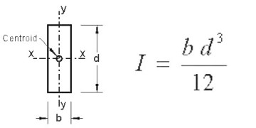
Calculus is usually used to find the moment of inertia (I) of an irregular section. However, a simple formula has been derived for a rectangular section, which is the most important section in this subject.
The formula for a rectangular section is:
Section Modulus
To calculate the bending stress in structural members (beams), a property called SECTION MODULUS is used to express the bending moment/stress relationship.
Each point within a cross-section of a beam will have a section modulus, this being the ratio of the second moment of inertia to the distance between a point within the section and the relevant axis.
In the Section shown opposite the section moduli of the point are:
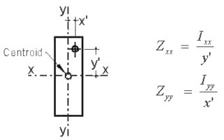
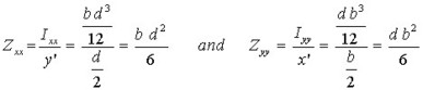
As the maximum stress occurs in the extreme outer fibres, this distance is needed for the calculation of the maximum bending stress. Following from this we can conclude that for a rectangular section y' should be substituted with d/2 and x' with b/2 respectively in the above formula to find the stress in the extreme outer fibres. I of a rectangular section is equal to the breadth times depth cubed over 12. Substitute this in the formula gives:
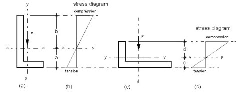
For asymmetric section the distance to the neutral axis is not the same to the extreme outer fibre and therefore two values for each axis exists. This is shown in the figure below.
|
(a) Angle upright position |
(b) Angle flat position |
For each axis (x-x and y-y) exists one moments of inertia (Ixx and Iyy) and as the distance to the outer fibre is different in angle position (a) and (b) there are two section modulus for each axis (x-x and y-y). The four section modulus, Zxx(t), Zxx(c) for position (a) and Zyy(t) and Zyy(c) for position (b), can be found by dividing the particular moment of inertia (I) by the distance a, b, c and d respectively. As can be seen the compression is greater than the tension. If you compare angle position (a) with (b), position (b) is not as effective as (a) because due to less depth beater stress in tension and compression occurs in (b).
Relationship between second moment of area and deflection
The stress in long span members is usually not the critical design criteria. Most standards impose a limitation on the deflection. It should not exceed for instance l/300 or l/500; that means the deflection of an nine meter (9 m) beam should be less than 30 or 18 mm respectively.
The following factors affect beam deflection:
- Load (usually in kN)
- Span in meter or millimeter
- Size and shape of beam (moment of inertia)
- Stiffness of material (modulus of elasticity)
- Constant factor (dending on load & support conditions)
Hopefully you'll remember some of the factors and by using a ruler you can easily find the missing factors. Anyway, your ruler can be an important tool in Structures. You can use it as small scaled beam, column etc. You can investigate structural issues like the difference between a single and continuous span, the disparity of material, deflection, bending/buckling, reaction etc. by simply using your ruler.
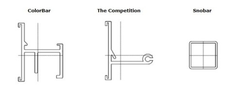
PROPERTIES OF COLOBAR: (with step at .005)
Area = 0.59 Ix = 0.15 Iy = 0.19
----------------
xmax = 0.89 ymax = 1.17 Wx = Ix/ymax Wy = Iy/xmax Wx = 0.13 Wy = 0.21
----------------
xmin = 0.70 ymin = 0.95 Wx2 = Ix/ymin Wy2 = Iy/xmin Wx2 = 0.16 Wy2 = 0.27
PROPERTIES OF THE COMPETITION (set at .01)
Area = 0.45 Ix = 0.12 Iy = 0.13
----------------
xmax = 1.16 ymax = 1.23 Wx = Ix/ymax Wy = Iy/xmax Wx = 0.10 Wy = 0.11
----------------
xmin = 0.55 ymin = 0.89 Wx2 = Ix/ymin Wy2 = Iy/xmin Wx2 = 0.14 Wy2 = 0.23
PROPERTIES OF SNOBAR (set at .01)
Area = 0.23 Ix = 0.03 Iy = 0.03
----------------
xmax = 0.50 ymax = 0.50 Wx = Ix/ymax Wy = Iy/xmax Wx = 0.07 Wy = 0.07
----------------
xmin = 0.50 ymin = 0.49 Wx2 = Ix/ymin Wy2 = Iy/xmin Wx2 = 0.07
_____________________________________________________________________
Specification Sheets
"Now In Stock"
SnoBar Colorbar WindBar
* Same Day Pickup
* Online Ordering
* Super Fast Shipping
* Colors in 4 Weeks